Wilson pre-selection gearbox
Home of the Wilson pre-selection gearbox
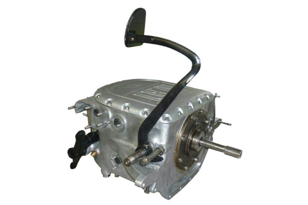
The Wilson Preselector Gearbox
The best known manufacturers of preselector gearboxes using the patent of the British engineer Walter Gordon Wilson were Armstrong Siddeley, E.N.V. Engineering Co. Ltd., Daimler and Talbot. The gearboxes from these manufacturers work on the same principle, i.e. manual epicyclic gearboxes with four forward and one reverse gear, and a neutral position. But they differ in construction in some important details.
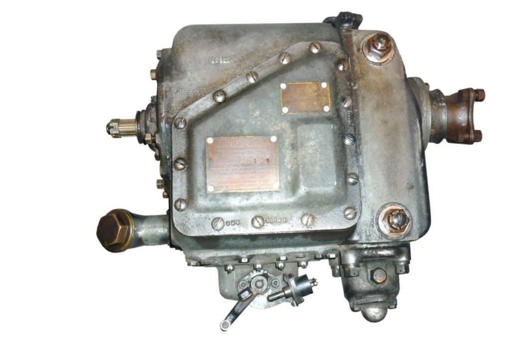
ENV 75
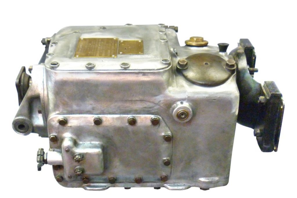
ENV 150
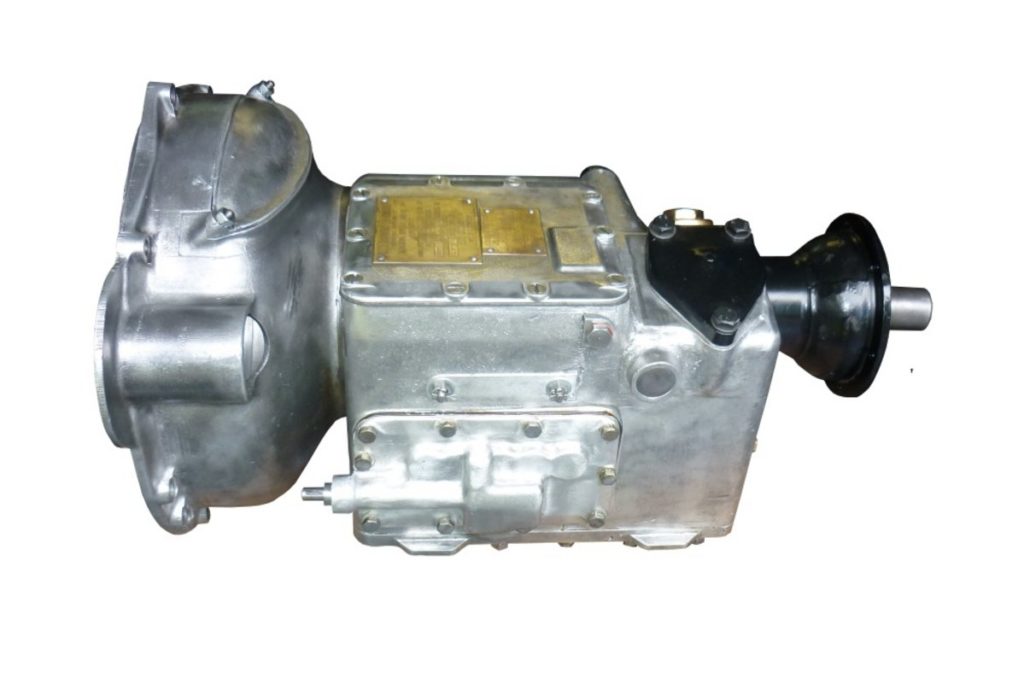
Daimler Lanchester
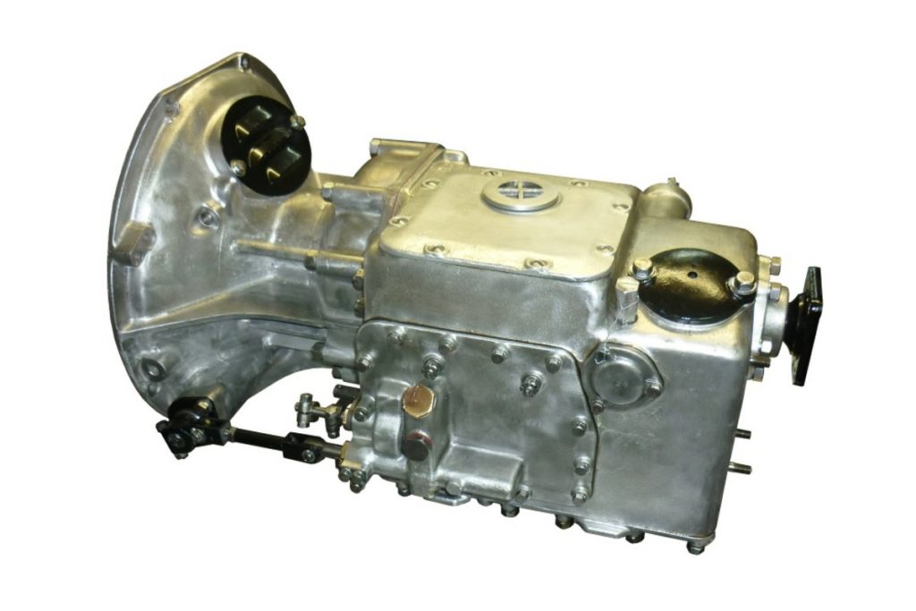
Daimler Straight 8
Armstrong Siddeley
Armstrong Siddeley Riley
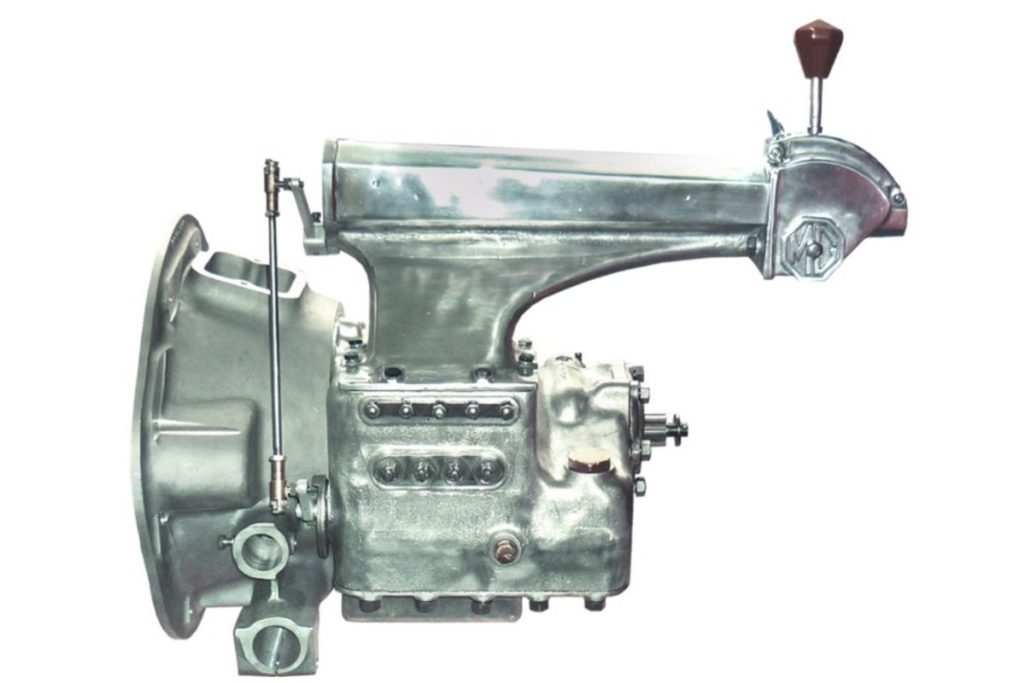
Talbot Lago
Talbot London
The 3 assemblies of the Wilson gearbox
The Wilson Gearbox comprises three subassemblies; the running gear, the brake harness, and the control mechanism, housed in an oil-tight casing. Running Gear. This consists of four epicyclic trains of gears interconnected so that different ratios and a reverse can be obtained by compounding the various trains. Top gear or direct-drive is provided by a cone or plate clutch. Oil pumps are also provided to ensure that lubricant is delivered to all parts of the somewhat intricate mechanism involved. First speed planet carrier acts as the driving member to the output shaft for all the forward gears. First gear is obtained by applying a brake to the first gear annulus/brake drum so that it is held stationary. The engine will then be turning the main sun gear so that the planet gears will be rolling inside the annulus, carrying their carrier round with them. As this carrier is fixed to the output shaft its motion is imparted to it and so to the rear axle. Second gear is obtained by holding the second gear annulus stationary by its brake. The main sun gear, still turned by the engine, causes the planet gears to revolve and turn their carrier. But this carrier is connected to the first gear annulus which therefore turns, speeding up the rotation of its planet gears and carrier, and this turning the output shaft faster than was the case in first gear, i.e. less reduction. Third gear is obtained by holding the third gear brake drum and sun gear stationary, for the sun gear of this train is integral with the brake drum. Further the annulus is an integral part of the second gear planet carrier which in turn is connected to the first gear annulus. The third gear planet carrier is connected to the second gear annulus so driving it in the dame direction oft he engine, i.e. increasing its speed. So the drive is taken back through the second gear planets and carrier and the first gear annulus both of which are speeded up. The result is to speed up the first gear planets and carrier, which are connected to the propeller shaft. In other words by interconnecting the second and third planetary gear trains, an increase of speed is obtained at the first annulus, which increases the speed of the planets and carrier. Top Gear. In top gear all the trains are locked together and revolve as one solid block, driving the output shaft at engine speed. This is brought about by the engagement of the driving member of the clutch (cone clutch or plate clutch) with the driven member, which is the drum and sun gear of the third gear train, so locking the third gear sun to the driving shaft. Thus all the sun gears will be revolving at the same speed since the first and second gear suns are fixed to the shaft and there cannot be any individual action of the various gear trains; all brake bands being loose round their annuli. Reverse. The first gear annulus is connected to the sun gear for the reverse gear train and hence drives it opposite to engine rotation. When the brake is applied to the reverse gear annulus, the reverse gear planet wheels, turned by the reverse sun gear connected to the first gear annulus (and therefore turning opposite tot he engine), carry with them the planet carrier in the opposite direction to the engine shaft. As the planet carrier is directly connected to the output shaft, the direction of rotation of the propeller shaft is reversed. Brake Bands. To put any required gear train into action the respective brake is applied to grip the annulus or drum. It will be appreciated that, in the course of time, wear will take place on the linings of the bands. Therefore, some means of adjustment is provided to eliminate the possibility of slipping. This is done automatically without any attention from the driver and ensures correct adjustment over very lengthy periods of service. Control Mechanism. A toggle linkage is used for tightening the brake bands to put a gear into operation. Each gear has a similar toggle linkage, put into or out of operation by the selector mechanism. The bus bar actuates the toggle linkage when a strut is engaged. Only one strut at a time, however, can be brought into engagement, each being pre-selected by the control lever on the steering column or centre shift. This lever is connected, through a suitable linkage, to the pre-selector mechanism mounted on a side plate (or inside the casing) of the gearbox. Thus, a camshaft is rotated according to the position of the control lever so the corresponding strut is pre-selected for engagement. But until the bus bar is lowered by deprssion of the operating pedal no engagement actually takes place. When, however, this pedal is depressed the strut selected drops into the slot in the lowered bus bar. When the pedal is released the rising bus bar forces the engaged strut upwards and this tightens up the brake band of the selected gear through the pull exerted on the brake pull rod.